Thursday, September 9, 2010

Injectors Testing

Injectors Testing


i was testing the fuel injectors so first i got the fuel injectors rails and i was testing it by the miultmeter and turns to ohms and then i was testing all 4 injectors and the restiance for each other is 0.14 ohms.. And the manufacturers is 1.5 so im sure the 4 injectors is okay nt that bad so it wil work fine.


the next bit i have wire up the injection with the 5v and i cant hear the clicking so i used ma had and i feel the clicking like the virbration. so i know all four of them are working.


The next bit is tesing bench cleaning fuel injectors


Good even cone is good conditon and very useful n good injectos


Offset pattern bit alright but it okay to use for a long term it could be nt mch voltage going thorugh the injectors

Poor atomissation is might be some faults on or the fuel pump not operating well.

Dribble my view i think the injector need to be replace no use and it wasting alot of fuel

the specifcation of maufacuter is injector leakage no drops per miniutes

the injecoter flow rates is 177cc per a minute


that picture it showing how good each injector going which pattern is it and which is the leakage like dirbble. 2 injecoted require attentions.

The fuel injectors numer one was good even cone same as the number 2 and 3. the number 4 was a poor atomistation. i think that has beeen damaged or it need to be clean up so it can be used again.


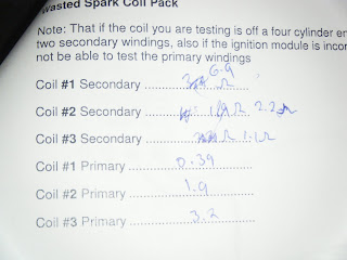
Testing Ignition Coils


i chosen 2 coils for tesing the voltages , primary and secondary primary.

so i was lookin the those 2 coil for specification and founds the number and match my reading wid ma muiiltmeter

this picture when i was testing two coils the muitmeter and set to 200ohms


the coil 1 when i was testin it was good and it can be seriveable bt the other coil number 2 cant be sevicable there some fualtys in the coils could be a crack or somthing

Now im testin the secondary windings

they all serviceable


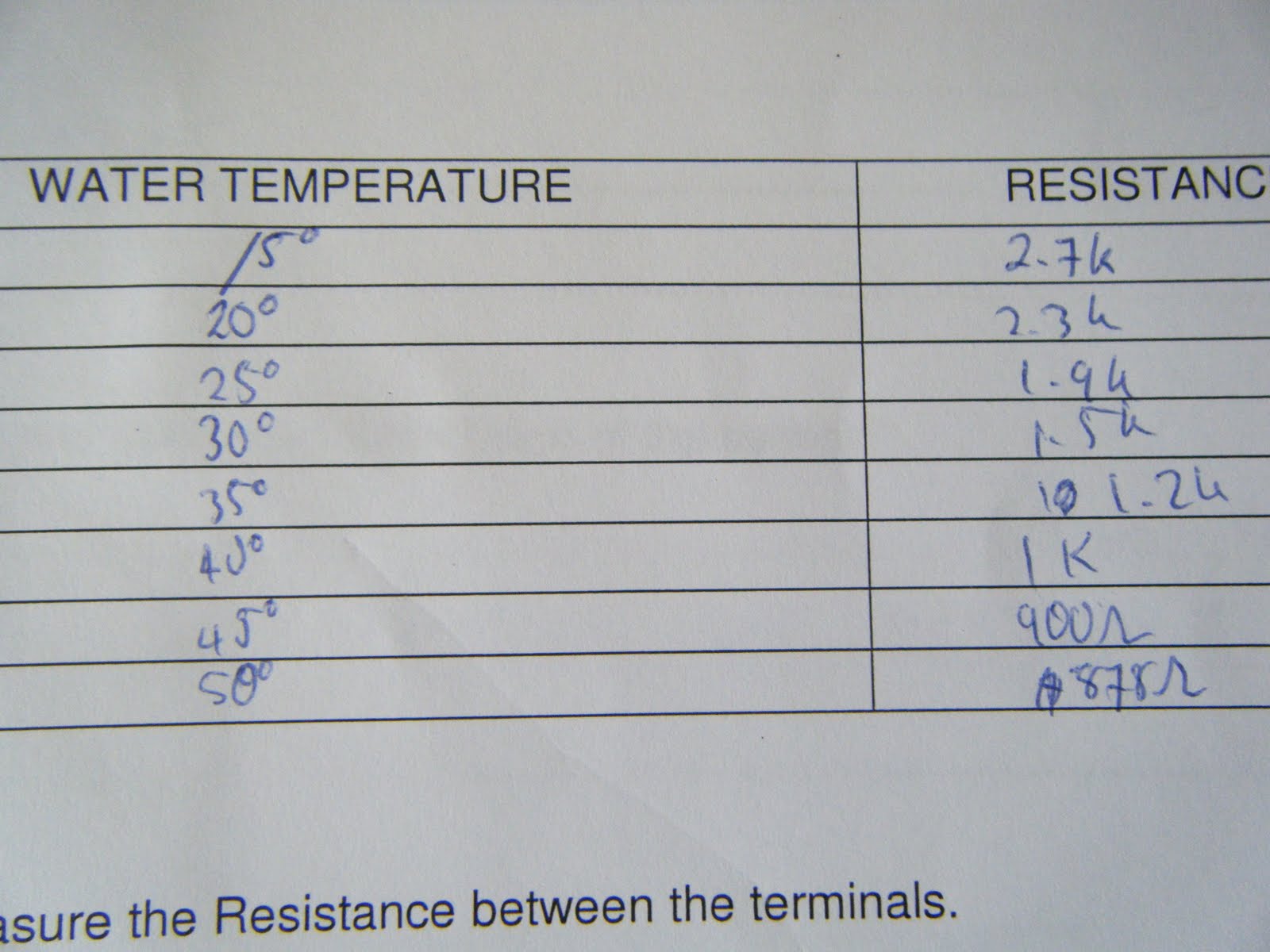
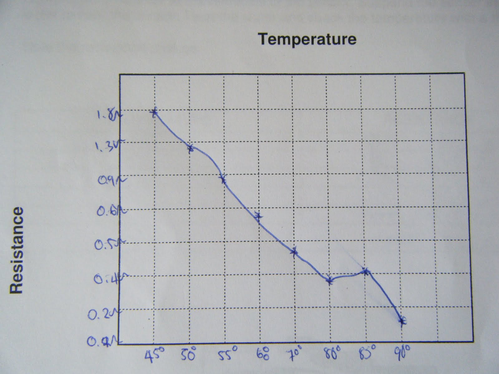
Testing Ballast Resistors


i have wire up the ballast in the big circuit board and has the ballast on itt

i calauted with the muiltmeter and find the reading for the ballast and the coils


Current draw 4.35v
Coil calcualted voltage drop 40.2v
Coil Measured Voltage drop 0.3v
Ballast resistor calcauted voltage drop 0.09v
Ballast resistor measured voltage drop 12.19v
i caulated the currernt draw and i got 4.35 ohms becasue dat the full ciruits with the ballast and the coil.


Wiring Ignition Systems


i wired the igniton module using a function generator to the trigger. using the colil and spark plug in the circuit to seee if they are firing or nt


atfer i done all the wiring it started to spark and it working then i turned the trigger bit higher and ths spark go faster and faster and making too mch noise for me though because it affected my hearing aids.


Wiring up and igniton module using a distrivutor to the trigger to the module

it was working fine i used the distrubutor and spin it and it was firing so it was working.and i have learnt a bit how it works for the ingnitions

Wiring up the wasted spark ingiton sytems using the funciton generator to the trigger the modules


this project i have done it was working well and it was two start plug firing and it shows the current n the voltages goi through the cicuirt to the start plug to ground.

Wiring up the coil over ingiton system using the funection generator to trigger the module.


it simlar as the first part i did but added 3 startplugs and has coil in it n trigger and also the Amp. Well 3 start plug was firing pefect!


The caultions ccurrent primary 2.5 ohms+ 2.2 ohms.


Tranistor max current is 3mA


12/3 =4ohms


Connect the cirucut up to the function genertator and the start plug


I choosen the wrong resistor 22 ohms it mean to be 2.2ohms and it was to find the datasheet online beacuase i havnt that before ,
Next time i will follower the data sheet correclty and find the right ones to used.

Saturday, September 4, 2010

Vane or flap air flow sensor/meter (AFM)

Vane or flap air flow sensor/meter (AFM)


Are your results within the manufacturer's specifications, why or why not?


Yes it does beacasue the readings is qiut the same to the manufactuers specifcition


The 5 volts is a referencer voltage supplied from the ECU. The singal voltage wil change when the van postion changes

Coolant Temperature Sensor


Measuring the Resistancer between the terminals


Does the Sensor meet the manufacture's specififcation why or why nt?

This is a ECT thermistor (engine coolant temperature)


it operation as the engine coolant temperature


Thermo Fan Switch Measuring the Resistance between the terminals


This is a Fan Switch and it switched at 90 degree. the circuit has a relay which is normally siwtched on.


This is a theromistor fan switch

the resistance changes becasue the water it gettin bit hotter and boiled so the resitence changes and going lower and lower

Air temperature sensors


Measuring the Resitance between the two terminals


This is a Air temperature sensor

the higher the air temperature gets the less dense the air becomes. The results of the Air and Coolant sensors well my view is simlar both of them but it depends on the temp n water boiling and how fast it goes and same goes for the switches


Knock Sensor


Explain why are reading a voltage from this sensor when we are not supplying a voltage to it


Because of the friction when you keep tapping it and it shows the wave rasing up and down the back sensor.


Speed Sensors


Checking on the Air Gap of the Distributor


that when i was using a feeler guage


atfer this i used a ocillosope to record the time and voltages showing


probe x volts x 5squares x 1/f = f

0.2v x 5v x 1/f = 1f

when a person was roatate the distributor like spining by hand and the use the oscilloscope on the postive side and show the reading when u spinning the distribuor

Hall Effect Sensors

i have done everything like wired up and things and it ddint works so i have used the voltmeter and the leture was helping me a bit and making me to try find where the fuaulty. and i check all the sensor everyhting was supply 12 volts then throgh hall sensor it was 5v so it a good ground. so i was wondering why it aint working. bt the finally it was the Hall Sensor faulty so i couldnt do the reading and findig the voltages everytime like clockwise until the voltages changes again.

Tuesday, August 24, 2010

Checking the Throttle Position Sensor

What type of TPS is this?
Linear sensor throttle


Explain it internal operation and why ur voltage changes?
If they turn the throttle to 45 dgree the reasding numbers increase same as the voltages


Now connect a Power Supply to your sensor and test the voltage output at different throttle angles.

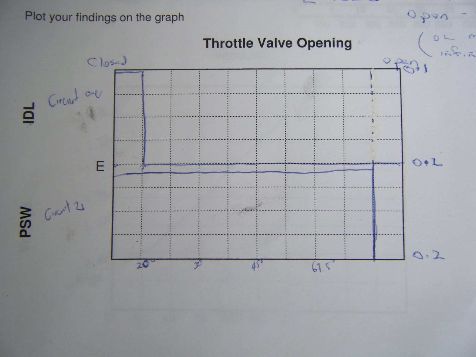
The Throttle Position Angle

Throttle Position Switch


Testing the Throttle Position Switch


When you are using the throttle and turn it to fully and the resistnce readings changes more than the closed throtttle


Those calucation i done they are match to the specifeications and i know why becasue i check the specifition and they are match and i used the vacuum pressure and voltmeter to find the readings and using 5v supply

The readings is the pressure not a vacuum

I used the vacuum pressure soon i pressed it the voltages drops down and the reading goes lower and lower when i keep pressing the vacuum presssure


Air Flow Mass Sensors(MAF)

What the voltages did you get when you first powered up the sensor without passing air over the sensor?

The voltages is 1.09


How did the voltages chang when air was passsed over the sensors?

The Air went in and the readings is 1.15v

I was testing the bocsh. The air flow mass sesor was match so the MAF specifcations

when I blew the air through the casing the temperature dropped and voltage increased